|
|
|
 |
Most of today's software applications share a common characteristic: the input/output data bandwidth is order(s) of magnitude smaller than the bandwidth required by the underlying algorithm sub-components' communication; also, multiple (relatively) independent processing functions are used, which makes them well suited for a parallel Multiple Instruction Multiple Data (MIMD) approach. Examples to illustrate this affirmation can be found in typical desk-top workstation applications (parallel spell checking, parallel sorting, parallel database searches, etc), in specialized engineering software (parallel matrix computation, parallel rendering of an image, parallel simulation of a structure's elements, etc), and also in communication and other DSP software (multiple channel processing, parallel split-spectrum processing, etc). The versatility of the MIMD approach also means it can implement Single Instruction Multiple Data (SIMD) algorithms by running the same program sequence on more processors, each accessing independently its own data structure. If the area ratio between the Instruction Control Unit and the Execution Units of each processor is relatively small, having multiple Instruction Control Units running the same sequence of operations will be a small price to pay for the versatility of the MIMD ensemble.
At the software level, multi-tasking and multi-threading operating systems have come with an answer to the parallel computing problem, while at the hardware level various attempts have been made to reconcile apparently exclusive conditions that are imposed on parallel architectures. The bottleneck traditionally associated with the MIMD paradigm is the way the system memory resources are shared. Parallel supercomputer architectures tried to address this problem over the years in many ways, ranging from the simple Shared Bus-based architecture, to complex Trees, Fat Trees, Rings, Hyper-structures, etc.
The parallel computing problem has also been addressed at a different level by the computer clusters and computer arrays approaches. In this case, sharing a common memory space between the processing elements (the computers) was no longer a requirement, but the approach is limited at one end by the communication speed between the computers inside a cluster, and at the other end by the processing power that can be packed in each computer. This, in turn, sends back to the multiprocessor computer problem that has to be resolved.
The approach outlined in this paper is based on the Data
Access Prediction Architecture (DAPA) concept that enables very low
memory conflict rates in a shared memory multiprocessor system.
The DAPA goal and concept are described, and the Parallel Vector Access
implementation (DAPA/Vector) is presented.
- note: the DAPA/Vector solution is specifically intended for vector data-based algorithms, and is not intended to serve as an architectural framework for general-purpose parallel machines; a more general DAPA solution targeting list-based machines is currently under investigation, using a Parallel List Access implementation (DAPA/List)
@toc@Table of contents@
DAPA Objective
The objective of the Data Access Prediction Architecture (DAPA) is defined as follows: to describe a very high bandwidth, multi-ported local memory, that can support N data accesses in the same clock cycle, without a proportional-with-N increase in the physical size of the memory module. Should such a memory architecture be defined, N processors could access the same physical memory resources without conflicting with each other, thus achieving the ultimate goal of multi-threaded parallel programming (as described by Fortune and Willie in "Parallelism in Random Access Machines", 1978): no latency, common addressing space, multi-processing.
Traditional multi-ported memories require, for a given memory size, an implementation area proportional with the number N of data ports. Although this solution can be viable for small, multi-ported register files, it is very inefficient for implementing a large local memory in a multi-processor system. For example, a 16-port, 1Mw memory module (to be connected to 16 processors) would have at least the size of a normal 16Mw memory module, thus making (for most of the cases) the cost of such a shared memory system prohibitive. By contrast, the DAPA only introduces a fixed area overhead over the shared memory module, thus making it attractive especially when the size of local memory required by the applications to be run in parallel is relatively large.
DAPA Structure
The DAPA building blocks are shown in Fig.1:
- the Port Cache Modules,
- the Data Access Prediction Engines,
- the Main Memory Access Arbiter,
- the Main Memory Module,
- the Parallel Data Channel
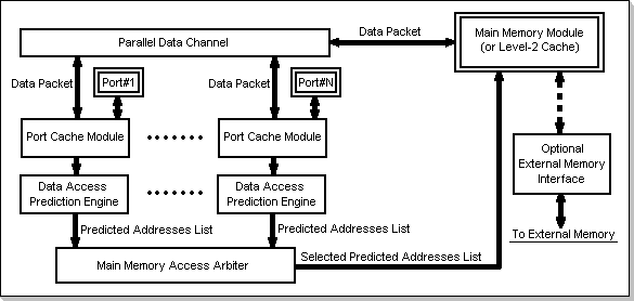
Fig.1: DAPA Structure
DAPA Functionality
In order to describe the functionality of DAPA, let us assume a given processor connected to a DAPA port, say port #1, requests to access data at a given address in the Main Memory Module. The Read requests and Write requests are treated differently inside the DAPA. For the purpose of this example, it will be assumed a Read access request is issued. It will also be assumed that the DAPA will be set to work in the Packet Update Mode (the various DAPA operating modes are targeted to most efficiently optimize different classes of applications; a description of these modes is beyond the scope of this presentation). The following steps will occur:
- First, the requested address is checked against the requesting processor port's local cache; if the address is found in the cache, the requesting processor will directly read the data from its cache, without any Main Memory Module referencing.
- If the requested address is not in the Port Cache, the following
actions are taken:
- the requested address is delivered to the Data Access Prediction Engine. This will create a Predicted Addresses List containing a number of addresses that are predicted to be requested by the processor during subsequent cycles.
- the Predicted Addresses List is passed to the Main Memory Access Arbiter. Based on a certain priority scheme, the Predicted Addresses List will eventually be forwarded to the Main Memory Module for effective data retrieval.
- the Main Memory Module delivers, on the Parallel Data Channel, a packet containing all the locations specified in the Predicted Addresses List, i.e. the actually-requested data, plus the predicted-to-be-requested data.
- the packet data will be transferred, via the Parallel Data Channel, to all the DAPA Port Caches Modules. The cache that originally requested the Main Memory Module access will thus be provided with the requested memory location, plus a set of locations that were predicted to be requested during subsequent cycles. The requesting Port Cache Module will load the entire packet, as it is assumed that further requests for data contained in the packet will be issued.
The DAPA mechanism, as described above, provides a way to effectively and efficiently utilize a wide-band communication channel; it is based on (1) predicting, at a certain moment in time, a set of future memory accesses, (2) requesting an access to all of them in parallel, and (3) assembling the data thus accessed on a wide band data bus.
Thus, after a request issued at one of the DAPA ports is served by means of a Main Memory Module access cycle, it will be very probable that subsequent requests issued by that port will find the requested data readily available in the local Port Cache Memory, thus allowing the Main Memory Module to serve other ports' requests. DAPA-aware compilers can also be very effective in improving the predictability of data references.
Architectural variations of DAPA will
consider the Data Access Prediction algorithm, the Main Memory Access
Arbiter priority schemes, the width of the Parallel Data Channel, the
size of the Port Cache Modules, the size of the Main Memory Module,
etc. Also, a direct extension of DAPA as presented in Fig.1 is obtained
by having the Main Memory Module act as a large Level-2 Cache for an
even larger External Memory.
The Parallel Vector Access Architectural Solution (DAPA/Vector)
Based on the statistics of data accesses in vector-based applications, a simple and straight-forward prediction technique can be derived. The architecture corresponding to this prediction technique is the Parallel Vector Access Architecture (DAPA/Vector).
In order to introduce the DAPA/Vector architecture, let us assume a DAPA port, say port#1, is to read a vector starting at a certain address in the Main Memory Module (i.e. the port will be requesting consecutive addresses inside the vector during subsequent cycles). First, the potential concurrent requests to the Main Memory Module coming from other DAPA ports will be resolved by the Main Memory Access Arbiter, based on a certain priority rule. Once port#1's request will be eligible for being served, the requested address will be retrieved from the main memory together with the next N-1 consecutive locations of that vector, and dispatched to port#1's local cache. Thus, the future N-1 data requests issued at port#1 will find the data readily available in the port's cache.
In order to illustrate the way this mechanism reduces Main Memory Module access conflicts, let us assume that all N ports in a N-port DAPA will request to read data from N vectors located in the Main Memory Module. Let us also assume, for the purpose of this example, that the ports' local caches can only hold N data elements, organized as one N-element cache line. The following steps will occur:
- Assuming that none of the ports' caches initially contains the requested data, N Main Memory Module requests will be pending (one for each port that is requesting data from the main memory). The Main Memory Access Arbiter will grant one of the ports' requests, say port#1, based on a certain priority scheme. Thus, the port#1 cache will be filled with N data elements: the actually requested data, plus the next N-1 elements in the vector. Consequently, during the following N-1 cycles, the data requested at port#1 will be readily available in the port's cache, allowing the Main Memory Access Arbiter to grant other ports' requests to access the main memory.
- Let us now assume that, during the second cycle, port#2 will be granted access to the Main Memory Module (by the memory access arbiter). The algorithm described for port#1 will be re-iterated for port#2, resulting in port#2's cache containing the data it requested, plus the next N-1 elements of the vector it is about to read.
- After the above-described algorithm is completed for each of the
N ports, i.e. N cycles since the first port#1 Main Memory Module
access, the N successive data elements that were stored in port#1's
cache will have all been accessed. At this moment in time, a request
from port#1 to read another vector element will issue a Main Memory
Module access request to the Main Memory Access Arbiter (as the vector
element could not be found in port#1's local cache). However, at this
time there will be no other pending Main Memory Module access requests,
since all the other ports still have the vector elements they need to
access in their local caches: port#2 still has one un-accessed vector
element in its cache, while port#N still has N-1 un-accessed vector
elements in its cache. Consequently, the port#1 request will be served
immediately, and without stalling the other DAPA ports operation.
Remark on the Number of Data Elements in a Port Cache Module Line
The example presented above describes the
way DAPA reduces Main Memory Module access conflicts, based on
N-element-sized Port Cache Modules (where N is the number of DAPA
ports). The data was assumed to be organized (in the caches) as one
N-element line, that is transferred as a packet through the Parallel
Data Channel. It can be seen that, for as long as the DAPA ports will
each be accessing successive elements in the Main Memory Module (each
port from a different main memory address), an increase in the number
of elements in a cache line beyond N will not contribute to lowering
the number of access conflicts any further (because the conflicts were
only occurring at the very beginning of the vector accesses, while
after the first N cycles no further memory conflicts occur). However,
if at some point in time, any of the DAPA ports will break the
linearity of the requested addresses sequence (i.e. start requesting
data from a different vector), this will trigger an immediate Main
Memory Module access request that will conflict with one of the other
N-1 ports' requests. This implies an "extra cycle" that should be
considered when analyzing the DAPA behavior. It can be seen that, in
such a case, a local Port Cache line size increase from N to N+1 would
eliminate the memory conflicts. Furthermore, increasing the cache line
sizes to N+M would help eliminate the memory conflicts that would occur
as a result of having M DAPA ports break the linearity of their memory
references (however, this is only useful if the break does not occur
simultaneously on more ports, in which case some conflicts will occur).
The conclusion to be derived from this remark is that the longer the
Port Cache Modules line size, the better the system will perform when
the ports will switch from accessing one vector in memory to another.
However, larger line sizes also imply a larger data packet to be
retrieved from the Main Memory Module, and a wider band Parallel Data
Channel. A tradeoff should be found between the two
requirements: increasing the caches line size and keeping the parallel
data channel's bandwidth within reasonable limits. For typical
DSP algorithms, a cache line size of 2 to 4 times the number of ports
is recommendable (further statistical studies on the line size of the
caches are currently being conducted).
Remark on the Number of Lines in a Port Cache Module
Although the number of lines in the Port
Cache Modules does not significantly influence the performance of the
DAPA/Vector during pure vector data processing, it will prove to have a
strong performance impact when more sophisticated algorithms are being
run. An example to illustrate the importance of having more than one
line in the DAPA ports' local caches is the FFT algorithm. During this
algorithm, data is accessed from memory using a special addressing
sequence, known as bit-reverse addressing. The sequence of bit-reverse
memory accesses actually translates into a succession of interleaved
addressing of a pair of vectors. In this case, by providing two lines
in the Port Cache Modules, it will be possible to maintain the same
performance as it was described for the pure vector situation (each of
the vectors in a pair will be stored in one of the cache lines). More
generally, by allocating P lines for a port's local cache, an
interleaved addressing of P vectors by the corresponding DAPA port will
be possible, while maintaining the full DAPA performance level
as described for the pure vector data addressing. The number of lines
in a Port Cache Module should be chosen by considering a compromise
between the DAPA efficiency and the size of the caches. A recommended
cache size for most typical DSP algorithms has been found to be 4 to 8
lines (further statistical studies on the number of cache lines are
currently being conducted).
Remark on Using Potential Main Memory Module Idle Cycles
A DAPA/Vector implementation with the
number of elements in a cache line greater than the number of ports
will allow for Main Memory Module idle cycles to occur, when all the
ports are synchronized and are accessing successive elements in memory.
However, these idle cycles can be used in a multi-line caches
configuration for filling additional Processor Cache Modules lines,
based on a certain algorithm. For example, it can be chosen that, for
each main memory idle cycle, a cache line will be pre-fetched in the
cache module that has the fewest un-accessed elements left in one if
its cache lines (and has not been pre-filled). If some conditions are
met, this mechanism can totally eliminate the overhead implied by
having one of the ports break its addressing sequence.
Remark on the Number of Data Access Prediction Engines
The general DAPA architecture, as shown in
Fig.1, uses separate Data Access Prediction Engines for each of the
processor Port Cache Modules, in order to allow for a flexible
definition of the prediction algorithm corresponding to each of the
ports. However, since the DAPA/Vector implements a single uniform
vector-based prediction scheme for all ports, a unique prediction
engine can be placed after the Main Memory Access Arbiter, replacing
the N separate engines (placed before the arbiter) in Fig.1. In this
case, the memory access arbiter will select one of the addresses
actually requested at the DAPA ports (instead of the Predicted
Addresses List), and pass it to the Data Access Prediction Engine.
Based on the received address, the prediction engine will generate the
Predicted Addresses List, and deliver it to the Main Memory Module for
accessing. It can thus be seen that, for the DAPA/Vector
architecture, the multiple Data Access Prediction Engines as they
appear in the general form of DAPA can be replaced with a single
prediction unit, positioned between the Main Memory Access
Arbiter and the Main Memory Module.
Remark on the DAPA/Vector Compatibility with Standard Programming Techniques
An important problem to be considered is the way the DAPA/Vector solution meets today's standard programming techniques challenge. It is known that a certain functionality to be implemented by a software application is being coded by decomposing it in a number of more elementary sub-components, usually packed in the form of functions. These functions, in turn, usually consist of more sub-components, again packed in the form of functions, and so on. Thus, a typical application execution sequence will consist of running pieces of sequential code, packed in functions, and occasionally performing function calls and returns. The most common programming methodology when coding a function is the use local variables, i.e. variables that are only visible within that function; the function receives, and can return, data via its argument list. Another method of passing data between the various functions in a program is based on the use of global variables; these variables are visible anywhere within the application. It is important to note that, for most of the cases, the number of references (made during a function evaluation) to global variables is substantially smaller than the number of references to the local variables. The way the local variables are stored in memory when a function is called is known as a stack frame structure; this is a linear sequence of addresses in memory that hold, successively, the local variables of the functions. Thus, it can be seen that the DAPA/Vector model is very well suited for handling stack frame data structures, as these consist of vector-arranged data.
DAPA/Vector – A Hardware Approach Example
A possible hardware implementation for the DAPA/Vector architecture is shown if Fig.2. This configuration assumes 16 DAPA ports, each 32 bits wide, and 1Mw Main Memory.
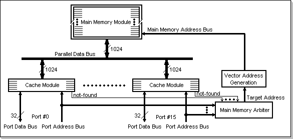
Fig.2: DAPA/Vector Hardware Implementation
Following is a brief description of the
DAPA/Vector components, as shown in Fig.2.
The Main Memory Module
The main memory is implemented as a 1 Mw block, organized in lines of 1024 bits. Each reference to a memory address will actually access a 1024-bit line in the main memory, containing a 32-word data vector (composed of 32 successive 32-bit words).
The Port Cache Modules
The ports' local caches are organized as 6 lines of 1024 bits, i.e. 6 lines of 32-word vectors. The cache modules are featured with a 1024-bit bus interface on the Parallel Data Bus side, and with a 32-bit bus interface on the DAPA ports side. When an access is requested at a DAPA port and the requested data is not found in the local port cache, this will cause an entire 1024-bit line (32 words), containing the requested 32-bit word, to be transferred between the Main Memory and the Port Cache (via the Parallel Data Bus).
The Main Memory Access Arbiter
The access arbiter resolves competing DAPA ports memory requests, that did not find the requested data in their local caches, based on a selectable priority scheme (random, rotary, table based, etc). It selects a Target Address to be accessed in the main memory.
The Vector Address Generator
The Vector Address Generator accepts the
32-bit word's Target Address from the access arbiter, and calculates
(by simply ignoring the least significant bits in the address) the line
number in the Main Memory Module that contains the requested
word-address. The memory reference to the specified word-address will
access a whole 32-word line.
Conclusions
This paper introduced the Data Access Prediction Architectures (DAPA) concept. It was shown how DAPA addresses the problem of limiting the number of conflicts between multiple processors sharing a common physical memory. An insight on a Parallel Vector Access architectural solution (DAPA/Vector) was given. The benefits and limitations of DAPA/Vector were presented, together with the way DAPA/Vector interacts with vector-based applications. The problem of the non-vector-data portions of typical software applications was also addressed, by presenting the corresponding behavior of a DAPA/Vector architecture in such situations.
It can be concluded that the
DAPA/Vector solution is an efficient and effective way of implementing
a multi-processor shared memory structure, when the processors are
known to be running calculation-intensive, vector data-based
algorithms. The DAPA/Vector multiprocessing solution is thus best
suited for today's high-end DSP applications, ranging from
multi-channel-based parallelism, to highly sophisticated algorithms
like Voice Recognition, Buffered Image Processing, etc.
© Information Technology Group
http://www.itgroup.ro
05/15/2000