Convolutional Coding and the Viterbi Decoder |
 |
General
Convolutional codes are used to add a certain amount of
redundancy when transmitting one or more data streams; the
receiver will use of the extra redundant information to recover
the potentially altered information.
While the convolutional encoding algorithm is essentially a simple
convolution of one or more data streams with two or more fixed
transfer functions, there are more ways to decode the thus-altered
data and extract the original information from it. One of the most
used convolutional decoders is the Viterbi Decoder.
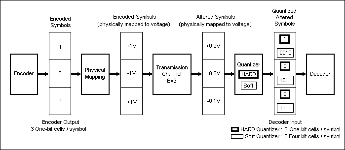
Fig.24 shows a simplified transmission chain that uses convoutional coding.

Fig. 24: Convolutional Coding Transmission Chain
The Convolutional Encoder
Example
A convolutional encoder functional diagram is depicted in Fig.25;
in this case the encoder has two data stream inputs, and three
data outputs, and is known as a Rate-2/3 Linear Convolutional
Encoder. The input data is fed into two shift registers (each
input data stream is fed to one shift register), and the output
data streams are computed by three weighted adders connected to
the shift registers' taps via a Connectivity Matrix. The
Connectivity Matrix switches implement the actual convolution
functions' coefficients (1s and 0s).

Fig. 25: Rate-2/3 Convolutional Encoder
As it can be seen, a convolutional encoder is a linear system, and it contains no feed-back routes; each input bit will affect a fixed number of bits at the encoder output. An important characteristic of convoultional encoders is that they operate on continuous data streams, as opposed to other classes of encoders that partition the input data into successive blocks (the latter classes are known as Block Encoders).
Convolutional Encoder Parameters
The number of output bits affected by an input bit is known as the
Constraint Length "K" of the encoder.
The number of Memory Cells in the encoder's longest shift register
(when there are more than one data inputs) is known as the
Encoder Total Memory "M".
The ration between an encoder's number of inputs and number of
outputs is known as the Encoder's Rate "R".
Remark
The transfer function for each output must obey certain
restrictions in order to have a convolutional code that can be
decoded (some convolution functions, known as "catastrophic",
generate un-reversable output data, i.e. the original data cannot
be recovered from the encoded data). Furthermore, the properties
of various convolution functions vary in a wide range as to the
amount of usable redundancy they add to the input data. The theory
behind the generation of "good" convolutional codes is beyond the
scope of this presentation.
Example
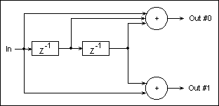
Fig.26 shows a convolutional encoder with one data input, and two
outputs. In this case the encoder rate is R=1/2, the Constraint
Length is K=3, and the total memory is M=2. The two convolution
functions have the coefficiets (1,1,1) for Output #0, and (1,0,1)
for Output #1.

Fig. 26: Rate-1/2 Convolutional Encoder
Note
It can be seen that for a rate R=1/x encoder, the number of memory
elements M is K-1 (i.e. K=M+1).
Data Symbols and the Transmission Channel
As shown in Fig.24, the convolutional coding data link establishes a connection between two sets of data ports ("Data In x" and "Data Out x"). The multiple data streams, although they can be independent, are coded and packed together by the encoder in order to be tranmitted on the Transmission Channel. The data format that is output by the encoder is referred to as Encoded Symols.
Fig.17 shows an example of an encoder-decoder (CoDec) transmission chain, and the various data formats used during the transmission at various positions along the chain. The encoder is assumed to have 3 ouputs (like the one in Fig.25).

Fig. 27: Data Formats Along a CoDec Transmission Chain
In a digital transmission, the Encoded Symbols will be binary B-bit numbers, where B is the bit-width of the Transmission Channel (for example, the Transmission Channel in Fig.27 used with the encoder in Fig.25 is 3 bits wide; note however that B-bit symbols can be physically trasmitted on a 1-bit channel via serialization). Each bit at the entry of the Transmission Channel will be represented by one of two discrete values (in Fig27 a voltage mapping is used for the physical data transmission: -1V for a logic 0 and +1V for a logic 1).
The Transmission Channel alters the Encoded Symbols, delivering Altered Symbols at its output. The Altered Symbols are no longer assumed to be limited to the set of discrete values generated by the encoder, i.e. the transmission channel can be viewed as delivering its output data using a couninuous numeric represenatation (the +0.2, -0.5, and -0.1 values in Fig.27).
At the decoder end of the transmission channel, the
continuous-representation Altered Symbols are first quantized by
the Quantizer (using a certain resolution and a certain
quantization curve) into Quantized Altered Symbols. The Quantized
Altered Symbols will consist of Q-bit binary representations of
its continuous input values (as they are received from the
Transmission Channel), where Q is the Quantizer bit-resolution.
The decoder will then attempt to identify the opriginal Encoded
Symbols, based on the Quantized Altered Symbols.
A Quantier with a one bit resolution (i.e. a single bit is derived
from each value received from the Transmission Channel), is known
as a Hard Decision Quantizer (the bold-framed values in Fig.27).
A multi-bit resulution Quantizer (that outputs a multi-bit
representation for each value received from the Transmission
Channel) is known as a Soft Decision Quantizer (the thin-framed
4-bit values in Fig.27).
Example
Let us consider a 6db-loss copper line as a Transmission Channel,
and two voltage levels to represent the encoder symbols' bits: -1V
for logic 0 and +1V for logic 1; in this case the Altered Symbols
received by the Quantizer (at the end of the copper line
transmission channel) will have a -0.5V value for logic 0, and
+0.5V value for logic 1.
If a Gaussian additive noise is present on the copper line, the
mean values received by the Quantizer for each transmitted logic 0
and logic 1 will still be -0.5V and +0.5V respectively, but the
successive individual values will vary around these two mean
values according to a Gaussian statistic, and having a dispersion
related to the S/N (Signal/Noise) ratio of the transmission line.
For example, when a succession of +1V binary 1s are transmitted on
the line, the Quantizer input will receive a succession of
+0.5V-cenetered values, having a Gaussian distribution and a S/N
ratio-related dispersion.
Remark
In the example in Fig27, each value transmitted on the channel is
received with heavy distorsion by the Quantizer; the distorsion
simulates a 6db-loss line and an additive noise. It can be seen
that, when using a hard decision Quantizer, the symbol that is
passed to the Decoder alreay contains a clear transmission error
(for a transmitted symbol [101], the decoder receives the symbol
[100]).
The Convolutions Decoder
There are many ways of decoding convolutional codes, each of them making use, in various extents, of the redundant information embedded in the encoded data stream in order to correct potential transmission errors. Each of these decoders share the following common charateristic: when fed with a data stream that is the direct result of applying a convolutional enconding scheme on a source data (i.e. when using a distorsion-free transmission channel, followed by a Hard Quantizer), the Convoultional Decoder will be able to recover the source data at its output.
The basic type of convolutional decoder will only accept as input
the direct result of a convolutional encoding algorithm; it will
signal an error condition if an invaid (i.e. altered) symbol is
pesented at its input. The more sophisticated classes of decoders
(including the Viterbi Decoder) will try to correct a
certain type of presumed transmission errors, based on an assumed
set of characteristcs for the transmission channel.
The Viterbi Decoder
The Vitrerbi Decoder is a "maximum likelyhood" decoder; this
means that every time an input symbol is identified as "invalid"
(i.e. it cannot be the direct output of a specified counvolutional
encoder, no matter what sequence has been fed into the encoder),
the decoder will try to assume the most likely symbol to have been
transmitted by the encoder.
The likelyhood criteria are established based on a number of
assumptions on the characteristics of the transmission channel.
The Viterbi Decoder asumes that the transmission channel is
memoryless (i.e. its chracteristics at a given moment do not
depend on the previous channel state), the transfer function of
the channel is linear (a non-linear function would produce
cross-modulation effects), the transfer function is
time-invariant, and a Gaussian additive noise is present on the
channel.
Note
Real-life communication channels have (more or less) different
characteristics than the ones mentioned above; for example they
may be non-linear channels (resulting in cross modulation
effects), time-varying (including fading and ionosphere
amplification effects), multi-path channels (echoes), athmospheric
noise (like lightning, etc). In each of these cases the Viterbi
Decoder will exhibit different performance levels in recovering
the original data that has been transmitted through the channel,
but in all cases it has proved to be one of the best known
data-recovery algorithms for convolutional codes.
The Viterbi algorithm tries to recover each incoming symbol by
taking into account all the previously-received symbols since the
beginning of a transmission, and also looking forward at the
next-to-come N symbols that are to be received.
The "forward-looking" ability of the Viterbi decoder is a
non-causal behaviour, so it's not physically possible to be
implemented as-such. Instead, the decoder will be allowed to
generate each output symbol with a delay of N relative to the time
the corresponding symbol was encoded and transmitted.
For example, consider the encoder transmits, at time T, an encoded symbol E[T]. The decoder will only generate the decoded output symbol D[T] corresponding to the encoded symbol E[T], at time T+N (i.e. D[T] will be calculated and output by the decoder with a delay of N relative to the time E[T] was transmitted). Thus, by the time T+N when the calculation of D[T] is performed, the decoder will have received the N symbols E[T+1] ... E[T+N] that followed E[T]. In this way the decoder can base its calculation of D[T] on both the corresponding encoded symbol E[T], and on the next N encoded symbols E[T+1] ... E[T+N] that follow E[T].
In order to calculate an ouput symbol, the Viterbi decoder uses a
special data structure that is updated each time a new encoded
symbol arrives; this data structure is known as the Viterbi
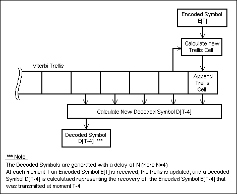
trellis (see Fig.28).
The Viterbi trellis is organized as a row of cells. Each time a
new encoded symbol arrives, a new cell is calculated and appended
to the trellis (see Fig.28).

Fig. 28: Viterbi Decoder Actions at Moment T
Using the above terminology, for each moment T, the main stages of the Viterbi algorithm are:
- receive a new encoded symbol E[T]
- update the Viterbi trellis based on the newly received encoded symbol E[T], and on the last cell in the trellis (in this way the last cell always contains "accumulated" information about the transmission until moment T)
- based on the updated Viterbi trellis, calculate a decoded symbol D[T-N] representing the recovery attempt for the encoded symbol E[T-N] that was transmitted by the encoder at moment T-N
- output the decoded symbol D[T-N]
Following is a detailed description of the Viterbi trellis, and
of the Viterbi algorithm stages. A Rate 1/2 Encoder (see Fig.26)
will be used to exemplify the descripition in two situations: a
Hard Quantizer based decoder, and an Infinite-Precision Quantizer
based decoder (i.e. very fine represenation of the received values
of the Altered Symbols)
The Viterbi Trellis Structure
Fig.29a represents a Viterbi trellis data structure corresponding
to a Rate 1/2 and K=3 encoder (Fig.26).
Each column in Fig.29a represents a Trellis Cell.
Each Trellis Cell is composed of a number H=2^(K-1) of Elements,
where K is the Constraint Length of the encoder (H is the the
height of each column in Fig.29a).
Each Trellis Cell Element is composed of the following Fields:
Encoder Implementation
Encoder Components
Encoder Usage
Decoder Implementation
Decoder Components
Decoder Usage
Implementation Remarks
Additional Modules used for Error Correction in Data Tramissions
Channel Equalizer
Interleaver